Iranian Classification Society Rules

< Previous | Contents | Next >
Section 4 Machinery installations
401. Power of main machinery
1. The requirements to the minimum required power
min
delivered to the propeller shaft of
Icebreakers and Arc class ships are given in from (1) to (4) depending on their class.
(1) The minimum required power delivered to the propeller shaft of Icebeakers shall be consistent with their class according to Sec. 1
(2) The minimum required power delivered to the propeller shaft of Arc1 class ship shall not be less than the lesser of values determined according to (3), (4). The minimum required power
delivered to the propeller shaft of Arc2 ~ Arc6 class ships shall be determined according to (3).
(3) Minimum required power
min
shall be determined by formula below.
min · · ∆
where,
min
= minimum required power (kW)
= 1.0 for a fixed pitch propeller
for propulsion plants with controllable pitch propeller or electric drive but not more than 1.
is the rake of the stem at the centerline(degrees) (see Ch 1, Fig 1.2) for a bulbous bow
The product × shall be taken as not less than 0.85. but not less than 1.0
= maximum breadth of the ship (m)
= displacement [t] of the ship on the maximum ice draught according to Ch 1,
202. 3
and are given in Table 3.38
Irrespective of the results obtained in calculating power, kW, shall not be less than
the power as per formula above, the minimum
10000 kW for Arc6 class ship 7200 kW for Arc5 class ship 5000 kW for Arc4 class ship 3500 kW for Arc3 class ship 2600 kW for Arc2 class ship 1000 kW for Arc1 class ship
Table 3.38 Value and
Displacement , t | Value | Arc class | |||||
Arc1 | Arc2 | Arc3 | Arc4 | Arc5 | Arc6 | ||
0.26 | 0.3 | 0.36 | 0.42 | 0.47 | 0.5 | ||
, kW | 740 | 2200 | 3100 | 4000 | 5300 | 7500 | |
≥ | 0.15 | 0.2 | 0.22 | 0.24 | 0.25 | 0.26 | |
, kW | 4040 | 5200 | 7300 | 9400 | 11600 | 14700 | |
(4) The Minimum required power
min
for Arc1 class ship, shall be determined as the maximum val-
ue calculated as per the formula given in Ch 1, 302. 2 for the upper ice waterline (UIWL) and
![]()
lower ice waterline (LIWL) as indicated in Ch 1, 202. However, the value of taken as below.
, , shall be
= 1.0 for Arc1 class ship
= 0 and = 0
2.
402.
(5) The reduction of the required output may be considered for a vessel having design features im- proving performance in ice conditions. Such features are to be documented, either by means of model tests or full scale measurements.
In Icebreakers and Arc3 ~ Arc6 class ship, turbines and internal combustion engines with mechan- ical transmission of power to the propeller may be utilized as main engines, provided use is made of the devices to protect turbines, reduction gears of gas turbine geared sets and diesel-engine geared sets against the loads exceeding the design torque determined with regard to operation of such ships under ice conditions in compliance with the requirements of 404. 2.
Shafting
1. General
In Icebreakers and Arc class ships, the propeller shafts shall be protected from ice effects.
2. Diameters of shafts
The diameters of value indicated in
shafts in Icebreakers and Arc class ships shall exceed the design diameters by
Table 3.39. The diameter of propeller shafts, in mm, for Icebreakers and Arc
class ships shall, besides, meet the following condition in way of aft bearings.
≥
where,
= factor equal to
10.8 for propeller boss diameter equal or less than 0.25D (D is the propeller diameter)
11.5 for propeller boss diameter greater than 0.25D
= actual width of expanded cylindrical section of the blade on the radius of 0.25R for unit-cast propellers and of 0.35R for controllable pitch propeller (m)
= maximum thickness of expanded cylindrical section of the blade on the radii given
for
= tensile strength of the blade material (MPa)
= yield stress of propeller shaft material (MPa)
![]()
Table 3.39 Increase of shaft diameter, %
Shaft | Arc class | Icebreakers | |||||
Arc1 | Arc2 | Arc3 | Arc4 | Arc5, Arc6 | Center shaft | Side shaft | |
Intermediate and thrust | 8 | 12 | 13.5 | 15 | (1) | 18 | 20 |
Propeller | 15 | 20 | 25 | 30 | (1) | 45 | 50 |
Note: (1) Subject to special consideration by the Society in each particular case. | |||||||
![]()
3. Keyless fitting of propellers and shaft couplings
When fitting the keyless shrunk assembly, the axial pull-up of the boss in relation to the shaft or intermediate sleeve, as soon as the contact area between mating surfaces is checked after eliminat- ing the clearance, shall be determined by the following formula.
where,
= axial pull-up of the boss in the course of fitting
= material and shape mula,
factor of the assembly (MPa-1), determined by the following for-
For assemblies with a steel shaft having no axial bore, the factor may be obtained from Table 3.40 using linear interpolation.
= modulus of elasticity of the boss material (MPa)
= modulus of elasticity of the shaft material (MPa)
= Poisson's ratio for the boss material
= Poisson's ratio for the shaft material (for steel =0.3)
= mean factor of outside boss diameter
= mean factor of shaft bore
= mean outside shaft diameter in way of contact with the boss or intermediate (cm)
= mean internal boss diameter in way of contact with the shaft or intermediate (cm), refer to Fig 3.11
without intermediate sleeve,
sleeve sleeve
, ,
with intermediate sleeve,
≠ , ≠ , ≠
for the boss
therefore therefore ≠
for the shaft
= active length of the shaft cone or sleeve at the contact with the boss (cm)
= taper of the boss
= power transmitted by assembly (kW)
= speed (rpm)
= factor for ice strengthening according to Table 3.41
= propeller thrust at ahead speed (kW)
= thermal coefficient of liner expansion of the boss material ( )
![]()
= thermal coefficient of liner expansion of the shaft material ( )
![]()
= temperature of the assembly in the course of fitting ( )
= 1 for assemblies without intermediate sleeve
= 1.1 for assemblies with the use of intermediate
For Arc class ships, the value shall be chosen as the greater of the results culations for extreme service temperatures, i.e:
for for
obtained from cal-
Table 3.40 Factor
Factor × , MPa-1, Steel shaft w=0, × MPa,
Factor y | Copper alloy boss | with , MPa | Steel boss with × | |||||
× | × | × | × | × | × | × | ||
1.2 | 6.34 | 5.79 | 5.34 | 4.96 | 4.63 | 4.34 | 4.09 | 3.18 |
1.3 | 4.66 | 4.26 | 3.95 | 3.66 | 3.43 | 3.22 | 3.04 | 2.38 |
1.4 | 3.83 | 3.52 | 3.25 | 3.03 | 2.83 | 2.67 | 2.52 | 1.98 |
1.5 | 3.33 | 3.07 | 2.83 | 2.64 | 2.48 | 2.34 | 2.21 | 1.74 |
1.6 | 3.01 | 2.77 | 2.57 | 2.40 | 2.24 | 2.12 | 2.01 | 1.59 |
1.7 | 2.78 | 2.48 | 2.38 | 2.22 | 2.09 | 1.97 | 1.87 | 1.49 |
1.8 | 2.62 | 2.38 | 2.23 | 2.09 | 1.97 | 1.86 | 1.76 | 1.41 |
1.9 | 2.49 | 2.29 | 2.13 | 1.99 | 1.88 | 1.77 | 1.68 | 1.35 |
2.0 | 2.39 | 2.20 | 2.05 | 1.92 | 1.80 | 1.70 | 1.62 | 1.29 |
2.1 | 2.30 | 2.13 | 1.98 | 1.86 | 1.74 | 1.65 | 1.57 | 1.25 |
2.2 | 2.23 | 2.06 | 1.92 | 1.79 | 1.69 | 1.60 | 1.53 | 1.22 |
2.3 | 2.18 | 2.01 | 1.88 | 1.75 | 1.65 | 1.57 | 1.49 | 1.19 |
2.4 | 2.13 | 1.97 | 1.84 | 1.72 | 1.62 | 1.54 | 1.46 | 1.17 |
Table 3.41 Factor
Assembly | Arc class | Icebreakers | |||||
Arc1 | Arc2 | Arc3 | Arc4 | Arc5, Arc6 | Centre shaft | Side shaft | |
Propeller with shaft | 1.15 | 1.20 | 1.25 | 1.30 | (1) | 1.45 | 1.50 |
Coupling with shaft | 1.08 | 1.12 | 1.135 | 1.15 | (1) | 1.18 | 1.20 |
Note: (1) Subject to special consideration by the Society in each particular case. | |||||||
![]()
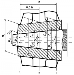
Fig 3.11 Details of propellers and shaft couplings
(2) When assembling steel couplings and shafts with cylindrical mating surfaces, the interference fit ( , cm) shall be determined by the following formula.
Other terms are as defined in (1).
(3) For propeller bosses and half-couplings in keyless assemblies with the shafts, the following con- dition shall be met.
≤
= shape factor of the boss determined by the formula
The factor A may be obtained from Table 3.42 by linear interpolation. for assemblies with conical mating surfaces.
for assemblies with cylindrical mating surfaces.
= actual pull-up of the boss in the course of fitting at a temperature
,
≥ (cm)
= actual interference fit of the assembly with cylindrical mating
surfaces,
≥ (cm)
= yi ld stress of the bo s mat ria MPa)
![]()
표 3.42 Factor
1.2 | 6.11 | 1.9 | 2.42 |
1.3 | 4.48 | 2.0 | 2.33 |
1.4 | 3.69 | 2.1 | 2.26 |
1.5 | 3.22 | 2.2 | 2.20 |
1.6 | 2.92 | 2.3 | 2.15 |
1.7 | 2.70 | 2.4 | 2.11 |
1.8 | 2.54 |
403. Propellers
1. Materials of propellers
Copper alloys of Type CU3 and Type CU4 are not admitted for propellers in Icebreakers and Arc4
~ Arc6 class ships.
2. Propellers blade thickness
(1) Propeller blade thickness is checked in the design root section and in the blade section at the radius r = 0.6R where R is propeller radius. The location of the design root section is adopted as follows.
(A) Solid propellers - At the radius 0.2R where the propeller boss radius is smaller than 0.2R,
and at the radius 0.25R where the propeller boss radius is greater than or equal to 0.2R.
(B) Detachable blade propellers - At the radius 0.3R, the values of the factors and adopted as in the case of r = 0.25R.
(C) CPP - At the radius 0.35R.
In solid propellers, detachable-blade propellers and CPP, the maximum thickness , in an expanded cylindrical section shall not be less than following formula.
mm, of
where,
= coefficient to be determined from the nomograph in Fig. 3.12 depending on the relative radius r/R of design section and the pitch ratio H/D at this radius (for a CP-propeller, take the pitch ratio of the basic design operating condition)
= coefficient obtained from Table 3.43
= shaft power at the rated output of the main propulsion engine (kW)
= number of blades
= width of the expanded cylindrical section of the blade on the design radius (m)
, but not more than 570 MPa for steels and not more than 610 MPa for copper alloys
= tensile strength of blade material (MPa)
= speed at the rated output (rpm)
= coefficient of centrifugal stresses to be determined from Table 3.44
![]()
= blade rake (mm)
![]()
Table 3.43 Coefficient
Arc class | Icebreakers | |||||
Arc1 | Arc2 | Arc3 | Arc4 | Arc5, Arc6 | Centre propeller | Side propeller |
11.2 | 12.5 | 13.2 | 14 | (1) | 16 | |
Notes 1. If reciprocating engines with less than four cylinders are installed in the ship, shall be increased by 7 per cent. 2. For reciprocating engines fitted with hydraulic or electromagnetic couplings, may be reduced by 5 per cent. 3. (1) through (2) in this table are subject to the following (1) Subject to special consideration by the Society in each case. (2) = shaft power, kW. | ||||||
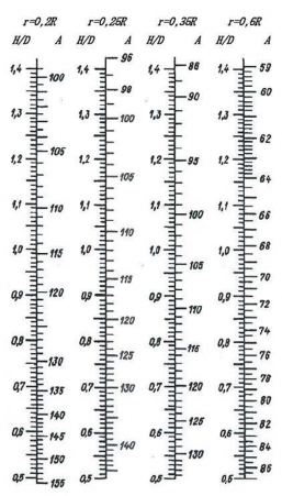
Fig. 3.12 Factor
![]()
Table 3.44 Coefficient
r / R | c |
0.20 | 0.50 |
0.25 | 0.45 |
0.35 | 0.30 |
0.60 | 0 |
![]()
Table 3.45 The blade tip thickness
Arc class | Icebreakers | |||
Arc1, Arc2 | Arc3 | Arc4 | Arc5, Arc6 | |
(2) | ||||
Note: (1) = diameter of the propeller (2) Subject to special consideration by the Society in each case. | ||||
(2) The blade tip thickness at the radius D/2 shall not be less than provided in Table 3.45. The leading and trailing blade edge thickness measured at 0.05 of the blade width from the edges shall not be less than 50 per cent of blade tip thickness.
(3) The blade thickness calculated in accordance with (1) and (2) may be reduced (e.g. for blades of particular shape), provided a detailed strength calculation is submitted for consideration to the
Society.
(4) In Icebreakers and Arc class ships, the stresses in the most loaded parts of pitch control gear shall not exceed yield stress of the material, if the blade is broken in direction of the weakest section by a force applied along the blade axis over 2/3 of its length from the boss and later-
ally over 2/3 from the blade spindle axis to the leading edge.
3. Propeller boss and blade fastening parts
(1) Fillet radii of the transition from the root of a blade to the boss shall not be less than 0.04D on the suction side of the blade and shall not be less than 0.03D on the pressure side. If the blade has no rake, the fillet radius on both sides shall be at least 0.03D. Smooth transition from the blade to the boss using a variable radius may be permitted.
(2) The propeller boss shall be provided with holes through which the empty spaces between the boss and shaft cone are filled with non-corrosive mass; the latter shall also fill the space inside the propeller cap.
(3) The diameter of the bolts (studs), by which the blades are secured to the propeller boss or the internal diameter of the thread of such bolts (studs), whichever is less, shall not be less than that determined by the following formula.
where,
k = 0.33, in case of three bolts in blade flange, at thrust surface 0.30, in case of four bolts in blade flange, at thrust surface 0.28, in case of five bolts in blade flange, at thrust surface
s = the maximum actual thickness of the blade at design root section (refer to 2. (1)) (mm) b = width of expanded cylindrical section of the blade at the design root section (m)
= tensile strength of blade material (MPa)
= tensile strength of bolt/stud material (MPa)
d = diameter of bolt pitch circle; with other arrangement of bolts, where
= the
distance between the most distant bolts (m)
(4) The securing devices of the bolts(studs), by which the blades are fastened to the detach- able- blade propellers of Arc class ships, shall be recessed in the blade flange.
4. Controllable pitch propellers
(1) The pitch control unit shall be designed so as to enable turning the blades into ahead speed position, shall the hydraulic power system fail. In multi-screw ships with Arc class of Arc1, this
![]()
(2) In ships with a CP-propeller, in which the main engine may become overloaded due to partic- ular service conditions, it is recommended that automatic protection against overloading be used for the main engine.
(3) The time required for the blades to be turned over from full ahead to full astern speed position with main machinery inoperative shall not exceed 20 s for CP-propellers up to 2 m in diameter
including, and 30 s for CP-propellers with diameters over 2 m.
(4)
In the gravity lubrication systems of CP-propellers, the gravity tanks shall be installed above the deepest load waterline and be provided with level indicators and low level alarms.
(5) The sealings fitted to the cone and flange casing of the propeller shaft (if such method of con- nection with the propeller boss is used)shall be tested to a pressure of at least 0,2 MPa after
the propeller is fitted in place. If the above sealings are under pressure of oil from the stern-
tube or the propeller boss, they shall be tested in conjunction with testing of the sterntubes or propeller boss.
(6)
After being assembled with the blades the boss of a CP-propeller shall be tested by internal
pressure equal to a head up to the working level of oil in gravity tank, or by a pressure cre- ated by the lubricating pump of the boss. In general, the test shall be made during blade
adjustment.
404. Power transmission system
1. In the strength calculation for gear of Pt 5, Annex 5-4 of the Guidance Relating to the Rules for the Classification of Steel Ships, the application factor , which accounts for externally
generated overloads on the gearing, is
dures for its determination.
chosen from Table 3.46 in the absence of special proce-
Table 3.46 Application factor
Type of gearing | Engine | Type of coupling on input shaft | max | |
Main propulsion | Electric motor | Any type | 1.0 | 1.1 |
Turbine | Any type | 1.0 | 1.1 | |
Internal com- bustion engine | Hydraulic or equivalent coupling | 1.0 | 1.1 | |
High elastic (flexible) coupling | 1.3 | 1.4 | ||
Other types | 1.5 | 1.6 | ||
Auxiliary | Electric motor | Any type | 1.0 | 1.1 |
Turbine | Any type | 1.0 | 1.1 | |
Internal com- bustion engine | Hydraulic or equivalent coupling | 1.0 | 1.1 | |
High elastic (flexible) coupling | 1.2 | 1.3 | ||
Other types | 1.4 | 1.5 |
For ships strengthened for ice navigation, the factor for main gearing is determined as a product of · ′ where ′ is obtained from Table 3.47.
2. For Arc class ships, the torque of the shafts, pinions, wheels of main gearing, shall be calculated by formula below.
′
Where,
′ = refer to Table 3.47
![]()
= torque of pinion at the maximum longacting load (Nㆍm)
![]()
Table 3.47 Factor ′
Factor | Ship class | ||||
Arc1 | Arc2 | Arc3 | Arc4 ~ Arc6, Icebreaker3, Icebreaker4 | Icebreaker5, Icebreaker6 | |
′ | 1.25 | 1.5 | 1.75 | 2.0 | 2.5 |
3. The elastic and disengaging couplings intended for Arc class ships shall satisfy the requirements of
Par 2.
405. Steering gear
Main steering gear of Icebreakers and Arc class ships shall be provided with a device to prevent the ice overload of turning mechanism.
406. Torsional vibration
1. Torsional vibration calculations
Torsional vibration calculations shall be prepared both for the basic variant and for other variants and conditions possible in the operation of the installation, as follows.
(1) Maximum power take-off and idling speed (with the propeller blades at zero position)for in- stallations comprising CP-propellers or vertical axis propellers.
(2) Individual and simultaneous operation of main engines with a common reduction gear.
(3) Reverse gear.
(4)
Connection of additional power consumers if their moments of inertia are commensurate with the inertia moments of the working cylinder.
(5) Running with one cylinder missfiring, for installations containing flexible couplings and reduc-
tion gear; to be assumed not firing is the cylinder the disconnection of which accounts to the greatest degree for the increase of stresses and alternating torques.
(6) Damper jammed or removed where single main engine installations are concerned.
(7) Flexible coupling blocked due to breakage of its elastic components (where single main engine installations are concerned).
2. Permissible stresses for crankshafts
(1) total stresses due to torsional vibration under conditions of continuous running shall not exceed the values determined by the following formulas.
For main engine crankshafts of Icebreakers and of Arc class ships within the speed range (0.7
~ 1.05) , and the crankshafts of engines driving generators and other auxiliary machinery for essential services within the speed range (0.9 ~ 1.05) ,When calculating a crankshaft in accord- ance with Pt 5, Annex 5-3 of Guidance Relating to the Rules for the Classification of Steel Ships,
± ----------------------------------------- (1)
When calculating a crankshaft by another method,
± -------------------------- (2)
For main engine crankshafts of Icebreakers and of Arc class ships within the speed range low- er than 0.7 , and the crankshafts of engines driving generators and other auxiliary machinery for essential services within the speed range lower than 0.9 ,
![]()
± -------------------------- (3)
Or,
±
--------------- (4)
where,
= permissible stresses (MPa)
the maximum alternating torsional stress determined during crankshaft calcu- lation from Pt 5, Annex 5-3, Par 2, (2) of Guidance Relating to the Rules for the Classification of Steel Ships.
= tensile strength of shaft material (MPa). When using materials with the ten- sile strength above 800 MPa, = 800 MPa shall be adopted for calculation purposes.
speed under consideration (rpm). For tugs, trawlers and other ships which main engines run continuously under conditions of maximum torque at speeds below the rated speed throughout the speed range, shall be adopted and formulas (1) and (2) shall be used. For the main diesel generators of ships with electric propulsion plants, all the specified values of shall, by turn, be adopted as , and in each of the ranges (0.9 ~ 1.05) , formulas
(3) and (4) shall be used for partial loads. rated speed (rpm)
: scale factor.
where,
= shaft diameter
(2) The total stresses due to torsional vibration within speed ranges prohibited for continuous run- ning, but which may only be rapidly passed through shall not exceed the values determined by the following formulas.
For the crankshafts of main engines,
For the crankshafts of engines driving generators or other auxiliary machinery for essential services,
-----------------------------------------
where,
= permissible stresses for speed ranges to be rapidly passed through (MPa)
= permissible stresses determined by one of formulas (1) to (4) of (1).
![]()
3. Permissible stresses for intermediate, thrust, propeller shafts and generator shafts
(1) Under conditions of continuous running, the total stresses due to torsional vibration shall not exceed the values determined by the following formulas.
For the shafts of Icebreakers and of Arc class ships within the speed range (0.7 ~ 1.05) , and generator shafts within the speed range (0.9 ~ 1.05) .
±
For the shafts of Icebreakers and of Arc class ships within the speed range lower than 0.7
, and generator shafts within the speed range lower than 0.9 ,
±
where,
= tensile strength of the shaft material (MPa). When using the material with the tensile strength over 800 MPa (for intermediate and thrust shafts of al-
loyed steel) and over 600 MPa (for intermediate and thrust and carbon-manganese steel, as well as for propeller shaft)
shafts of carbon
= 800 MPa
and = 600 MPa shall be assumed in the calculations accordingly.
= factor obtained from Pt 5, Ch 4, Table 5.4.1 of Rules for the Classification of Steel Ships.
= refer to Par 2. (1)
(2) The total stresses due to torsional vibration within speed ranges prohibited for continuous run- ning, but which may only be rapidly passed through shall not exceed.
For intermediate, thrust, propeller shafts and shafts of generators driven by the main engine
For the shafts of generators driven by auxiliary engines, refer to formula (5) of Par 2, (2).
4. Permissible torque in reduction gear
(1) For the case of continuous running or rapid passage, the alternating torques in any reduction gear step shall not exceed the permissible values established for the operating conditions by the manufacturer.
(2) Where the values mentioned under (1) are not available, the alternating torque in any reduction gear step for the case of continuous running shall satisfy the following conditions.
Within the speed range (0.7 ~ 1.05) for the main propulsion plants of Icebreakers and of Arc class ships,
≤
Within speed ranges lower than 0.7 , the permissible value of alternating torque will
![]()
specially considered by the Society in each case, but, in any case.
≤
where,
= average torque in the step under consideration at nominal speed (N/m)
= average torque at the speed under consideration (N/m)
For the case of rapid passage, the alternating torque value is subject to special consideration by the Society in each case.
5. Permissible torque and temperature of flexible couplings
(1) For the case of continuous running or rapid passage, the alternating torque in a coupling, rele- vant stresses in and temperatures of the flexible component material due to torsional vibration shall not exceed the permissible values established for the operating conditions by the manufacturer.
(2) Where the values mentioned under (1) are not available, the torque, stress and temperature val- ues permissible for continuous running and rapid passage shall be determined by the procedures approved by the Society.
6. Other installation components
(1) Under conditions of que)shall not exceed shafting couplings.
(2) Where, for generator
continuous running, the total torque (average torque plus alternating tor- the frictional torque in the keyless fitting of the propeller and shaft or
rotors, the Manufacturer's permissible values are not available, the alternat-
ing torque shall not exceed twice, in the case of continuous running, or six times, in the case of rapid passage, the nominal generator torque.
7. Torsional vibration measurement
(1) Data obtained from torsional vibration calculations for machinery installations with the main en- gines shall be confirmed by measurements. The measurements shall cover all the variants and operation conditions of the installation, for which calculations were made in accordance with Par 1, except emergency operation conditions listed in (6) and (7).
(2) The results of measurement obtained on the first ship (unit)of a series apply to all the ships (units) of that series, provided their engine-shafting-propeller(driven machinery) systems are identical.
(3) The free resonance vibration frequencies obtained as a result of measurement shall not differ from the design values by more than 5 per cent. Otherwise, the calculation shall be corrected accordingly.
8. Restricted speed ranges
(1) Where the shaft stresses, torques in some installation components or temperature of the rubber components of flexible couplings arising due to torsional vibration exceed the relevant permis- sible values for continuous running determined, restricted speed ranges are assigned.
(2) No restricted speed ranges are permitted for the speeds equal to or greater than 0.7 with spect to Icebreakers and of Arc class ships, and for (0,9 — 1,05) with respect to diesel
erators and other auxiliary diesel machinery for essential services. Where the main diesel gen-
erators of ships with electric propulsion plants are concerned, all the fixed speed values corre- sponding to the specified conditions of partial loading shall alternately be adopted for .
In icebreakers and ships with ice categories Arc7 to Arc9 fitted with a FPP, blade frequency
resonance shall be avoided within the range (0.5 ~ 0.8) .
(3)
For Icebreakers and of Arc class ships within the main engine speed range (0.7 ~ 1.05) , and for diesel generators within the speed range (0,9 —1,05) vibration dampers or
antivibrators
may be used to eliminate restricted speed ranges subject to special consideration by the Society
in each case.
407. Spare parts
Two spare propeller blades per one propeller completed with securing items for detachable propeller
![]()
and controllable pitch propeller are to be provided that are necessary for the case of eventual re- placement by the crew when afloat.
408.
1.
Seachests
Number and
and ice boxes
arrangement of seachests for the cooling water system shall comply with Pt 5, Ch 6,
703. of Rules for the Classificaion of Steel Ships. In Arc 1 and Arc2 class ships, one of the sea chests shall function as an ice box. In Icebreakers and Arc3 ~ Arc6 class ships, at least two sea chests shall be ice boxes. In Icebreakers and Arc class ships, the ice box design shall allow for an effective separation of ice and removal of air from the ice box to ensure reliable operation of the seawater system. Sea inlet valves shall be secured directly to seachests or ice boxes.
2. In Icebreakers and Arc class ships, provision shall be made for the heating of the seachests and ice boxes as well as of the ship side valves and fittings above the load waterline. For this purpose cooling water recirculation shall be used for ice boxes and sea chests. Ship side valves and fittings shall be supplied with heating medium through a non-return shut-off valve. The heating arrange- ments shall be so designed as to prevent the side valves and fittings and shell plating from being damaged under the influence of lowest temperatures. Electric heating systems with special heating cables may be used for valves heating. For ice boxes the recirculated water pipes shall be laid to the upper and lower part of the box, and the total sectional area of these pipes shall not be less than the area of the cooling water discharge pipe. For seachests, the diameter of the water re- circulating pipe shall not be less than 0.85 of the discharge pipe diameter.
409. Flexible hoses
Sleeves for cargo and fuel oil hoses of Arc class ships shall be subjected to cold endurance type tests. For this purpose samples of the hoses shall be kept at the temperature of -40 °C during 4 hour and be tested for elasticity by means of bending for 180° two times in the opposite directions around the adapter with a diameter of R, where R is a minimum bending radius; whereupon a vis- ual exam-ination is carried out. After freezing and bending no cracks shall appear on the internal and external surfaces of the sample. Where necessary, the sample may be cut along the axis for the internal surface inspection. On agreement with the Society, another method for freeze resistance test with allowance made for special structural features may be accepted.
410. Ballast, heel and trim systems
In Icebreakers and Arc class ships, the fore and after peaks, as well as structural wing tanks for water ballast, located above the waterline and in way of cargo holds, shall be provided with heat- ing arrangements. The double bottom tanks in way of cargo holds, intended for water ballast, are recommended to be fitted with heating coils.
411. Ventilation system
In Icebreakers and Arc class ships, precautions shall be taken to prevent admission of snow into the ventilation ducts. It is recommended to arrange the air intakes on both sides of the ship and to provide for heating arrangements.
412. Compressed air system
For Icebreakers and Arc3 ~ Arc6 class ships the total capacity of air receivers and the number of compressors for starting and reversing of the main engines is subject to special consideration by the Society in each case.
![]()